240 Volt 4 Lamp T5 Fluorescent Ballast Wiring Diagram

Led Tube Light Wiring Diagram With Images Led Fluorescent

Robertson 1p20132 Oem Pak Of 20 Fluorescent Eballasts For 2 F40t12

How To Bypass A Ballast 1000bulbs Com

What Are The Two Yellow Wires From A Ballast For Quora

Advance Fluorescent Ballasts Labels 101 Advance Ballast

Ge Lighting Ge454mvps90f Fluorescent Ballasts Crescent Electric
Remove the ballast from the.
240 volt 4 lamp t5 fluorescent ballast wiring diagram. Newer fluorescent ballasts are usually rated for both 120 volts and 277 volts. 4 lamp rapid start to retrofit wiring diagrams 4 lamp retrofit wiring diagrams ballasts to retrofit to one 4 lamp electronic t8 instant start ballast blue black white line lamp lamplamp red yellow blue 4 light t8 ballast wiring diagram circuit diagram maker 4 light t8 ballast wiring diagram further 2014 new hot sale electronic ballast along with phillip. Wiring diagram how to bypass ballast for led tube. Lamp lamp red photo control wiring diagram 208v 240v 277v 480v blk red line line photo control wht lampload red or wht blk blk yel compact fluorescent ballast wiring diagrams 1 1 lamp 2 2 lamp quad volt ballasts are factory wired for 277v input.
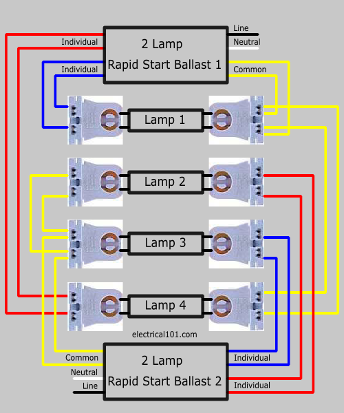
Cut back additional wiring on opposite side of ballast as the led tube lamp only requires power at one end. Each kit comes with pre wired non shunted g5 lampholders and a power quick connector to help reduce installation time and cost. The yellow wires are for lack of a better description are shared so pin 1 of lamp 1 and pin 1 of lamp 2 go one yellow wire. A wiring diagram is a streamlined standard pictorial representation of an electric circuit.
Pin 2 of lamp 1 and pin 2 of lamp 2 go to the other yellow wire. Truly we have been noticed that 4 lamp t5 ballast wiring diagram is being just about the most popular issue at this moment. Some are rated for only 120 volts others for only 277 volts used in commercial environments. Wiring fluorescent light ballast replacement wiring diagram and in 4 lamp t5 ballast wiring diagram image size 800 x 522 px and to view image details please click the image.
Its purpose is to show you step by step how to convert your current 4 foot t8 or t12 fluorescent tube light fixture to use the starled ballast. Notice how both the red and blue wires go to one lamp. So that we tried to uncover some terrific 4 lamp t5 ballast wiring diagram. It reveals the components of the circuit as streamlined forms and the power and also signal links in between the gadgets.
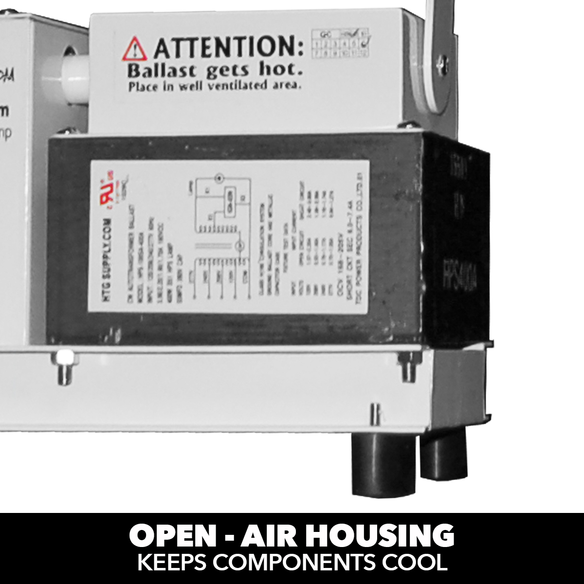
Before installation make certain supply and ballast voltages are compatible. With some 3 and 4 lamp series parallel ballasts if a single lamp in one branch fails the lamp s in the parallel branch will continue to operate. 4 lamp t8 ballast wiring diagram. Here s a larger view of the wiring diagram.
Assortment of fluorescent ballast wiring diagram. Is this how you have it wired. Maxlite t5 wiring harness is the ideal solution for retrofitting a 4 lamp fluorescent t5 fixture with type b ballast bypass led t5s. Non shunted g5 lamp holders pre wired for fast and easy installation.
Series ballasts can only be wired in series according to the diagram on the ballast.

How To Replace A Rapid Start Florescent Ballast Youtube

R 4s40 A Tp Ac Advance Magnetic Ballast 4 X F40t12 Lamps

3aaa Yz 239eaa T5 E 220 240v 2x39w Fluorescent Lamp Ac Electronic
240 Volt 4 Lamp T5 Fluorescent Ballast Wiring Diagram Wiring Diagram
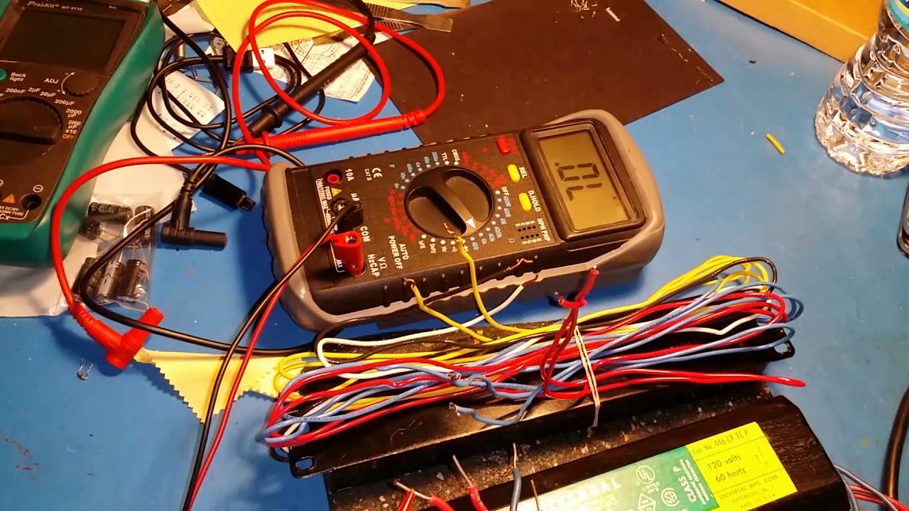
Fluorescent Fixture Ballest Test Youtube

How To Convert Fluorescent Tubes To Leds Using Ballast Bypass
400 Watt Hps Grow Light Shop 400w Hps Light For Indoor Growing
Fulham Pony Sugarcube Ballasts
Rapid Start Replacement Ballasts Ceiling Lighting Accessories

Keystone Ktps 80 1 Photocell Button Style
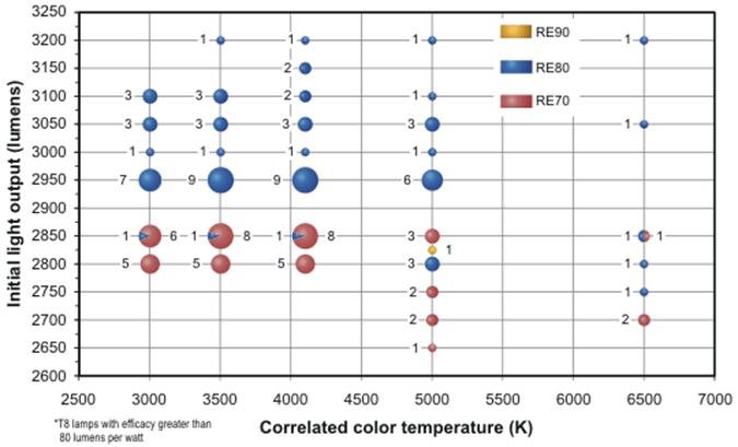
T8 Lighting What Is The Actual Lumen Output For T8 Fluorescent Bulbs

Top Quality 1 2 Inch Mini Pneumatic Air Impact Wrench Air Wrench

Hydrofarm Seedling Heat Mat 107w 48l X 20w Inches Hydrofarm
